BR British Rail Crimson & Cream
Crimson and Cream Crimson Cream Blood & Custard Blood Custard Blood and
Custard BR British Rail Crimson & Cream Crimson and Cream Crimson Cream
Blood & Custard Blood Custard Blood and Custard BR British Rail Crimson
& Cream Crimson and Cream Crimson Cream Blood & Custard Blood Custard
Blood and Custard
London,
Brighton & South Coast Railway
Crystal Palace ‘CP’
‘Elevated
Electric’ AC stock
|
CP
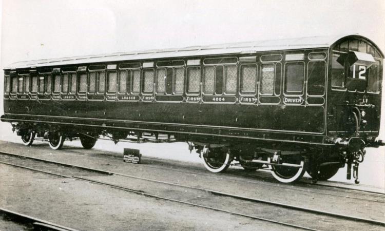
stock Driving Trailer Composite car 4004 in 1911 as delivered in LBSCR umber
livery. In April 1925 it was renumbered 9828 and received lined olive green. Note
the different door vents (with label above) for the three smoking
compartments. Rebuilt
for 3 Car Motor Units in May 1929 with body (into unit no.1742 as TC 9742)
written off in the Dorking Collision on 22nd December 1941 being separated
from underframe (into unit no.1733 as TC 9725) scrapped at Newhaven in August
1959. |
Around the turn of the century, the London, Brighton & South
Coast Railway (LBSCR) were concerned about falling traffic receipts in the
suburban area and also wished to make economies in the costs of working their
system. So, they began investigations into the feasibility of working their
trains electrically. Electric operation of trains was now becoming quite
practical and was indeed already in operation on a number of railways abroad
and the LSWR had commenced limited electric operation in 1898 in the Waterloo
& City Railway tube line.
The construction of further electrified tube railways in London
and the parallel electrification of some competing tramway routes also spurred
these investigations by the LBSCR and the company obtained an Act of Parliament
in July 1903 to enable it to electrify parts of its system. Philip Dawson was
retained as a consulting electrical engineer to investigate the most suitable
system and from an early stage it was agreed that the system chosen should be
suitable for use on possible future extensions of the system beyond the suburban
area. Dawson took into account an earlier report to the LBSCR board presented
in 1902 by the Chief Engineer which pointed out a number of disadvantages of
the third rail system for the LBSCR network and presented a report to the board
in July 1904 recommending the adoption of a single‑phase alternating
current system at nominal 6,700 volts using overhead contact wire. The system
was envisaged as suitable for the whole suburban network and with the
possibility of later extensions should this be required.
Dawson was instructed to prepare plans for electrification of
the lines between Battersea Park and Peckham Rye via the South London line and
contracts were let in April 1905, awarded to the Allgemeine Elektricitats-Gesellschaft
(AEG) of Berlin; this company sub‑contracting the overhead line work to
Messrs R. W. Blackwell & Company of London, who in turn sub-contracted
further with British Thomson‑Houston Co providing switchgear and Johnson
& Philips also Siemens Bros providing cabling. Soon after these contracts
were let, the LBSCR decided to extend the electrification scheme from Peckham
Rye into London Bridge and from Battersea Park into Victoria so that the whole
South London line route was covered, and further contracts were let to cover
these extensions in March 1906. The rolling stock provision for the line was
awarded to the Metropolitan Amalgamated Carriage & Wagon Company of
Birmingham.
|
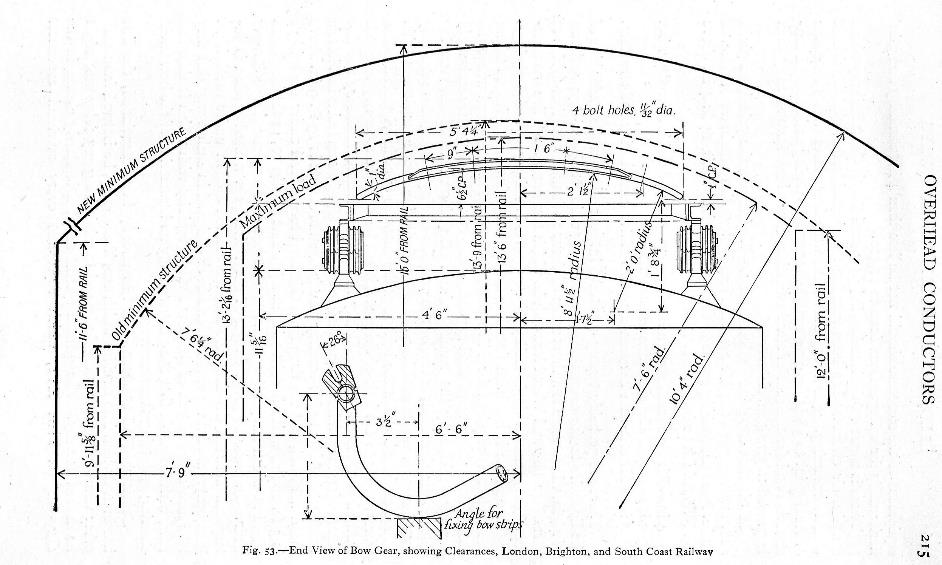
Bow Gear Clearances Diagram shewing the clearances for the train’s AC Bow
Collectors. |
The Overhead
Power for the system was obtained from the London Electric
Supply Corporation's generating station at Deptford and supplied at nominal
6,700 volts, 25 hertz via cables direct to a switch room at Queens Road,
Peckham and a distribution room at Peckham Rye. Power was then distributed via
lineside cables to switch cabins located at each station which supplied the
overhead equipment. Wherever possible the current supply arrangements allowed
one line to be isolated without having to isolate the adjacent track. The
overhead lines were suspended at a contact height of 16' above rail level,
though this was reduced under certain low bridges to 13' 9" (where
there were ‘Dead’ sections) whilst in the vicinity of the platforms at Victoria
and London Bridge the height was raised to 19' 9" to give greater
clearances as staff still had to go onto carriage roofs to lamp oil lit stock
or light gas lamps in some gas lit stock.
The contact wire was suspended from two catenaries; these being
located one to each side and away from the centre line of the track to avoid
damage to the insulators from the blast of locomotive chimneys. The catenaries
were made of 12 strand galvanised steel and the droppers from these to the
contact wire were formed as a stiff ‘V’ shape and were clipped to the contact
wire by phosphor bronze clips. Droppers were spaced every 10' and held the
copper contact wire off centre above the track with alternate deviations of
9" from the track centre line; this zig-zagging of the contact wire was
designed to prevent the wire wearing a groove into the bow collectors of the
trains.
The structures supporting the catenaries were mostly steel
lattice gantries, the catenaries passing above these structures and supported
on porcelain insulators, though there were some variations in the vicinity of
overbridges. The overhead gantries were usually spaced about 150' apart, though
some gaps were as small as 50' and the longest was 210' owing to siting
difficulties.
Minimum clearance around the contact wire was specified at 3",
though 4" was normally allowed, and the loading gauge height of the LBSCR
was set at 13' 6" so the minimum height of the contact wire had to be
set at 13' 9". As a consequence, there was a need for ‘Dead’ sections
with the wire at this height under five overbridges on the electrified lines.
Crystal
Palace Extension
The almost immediate success of the South London line
electrification scheme which commenced from 1st December 1909
in raising passenger numbers on this line, led to the LBSCR board to quickly
authorise the extension of electric working early in 1910. It was then planned
to electrify the lines from Victoria to Crystal Palace via Clapham Jct. and Balham.
The same main contractors who had been used for the South London scheme were
again contracted for this scheme.
Electrification work commenced at Battersea Park (junction for
the South London line) and only the two Local lines were electrified as far as
the south end of Clapham Jct. station, then all four lines were equipped to the
junction at Balham to allow an overtaking facility if required. The double
track through Streatham Hill to the junction at Crystal Palace were equipped
and the overheads were then taken into the London Bridge platforms at Crystal
Palace and just beyond the station to allow trains to reverse into the centre
sidings.
One of the sidings at Pigs Hill (Clapham Jct.) was electrified
to enable trains to be reversed there from the south whilst the Up Bay platform
was also equipped at Streatham Hill to enable trains from Victoria to reverse
there if required. Two of the sidings on the down side were also electrified
here for stock berthing.
Selhurst Maintenance Depot
Whilst this scheme was still in the planning stage, it was
decided to extend the electrification still further. The nearest suitable site
to the route for the building of a maintenance depot and berthing sidings was
identified between Norwood Junction and Selhurst stations and a carriage shed
and berthing sidings were laid out here with access from both the Norwood Jct.
and Selhurst ends. To gain access to these facilities, electrification was then
planned to be extended from the junction at Crystal Palace to Norwood Jct. and round
the spur to Selhurst.
Wires were carried beyond Selhurst towards Thornton Heath to
allow terminating trains to reverse back into the depot. The ‘Croydon’ bay
platforms along with the Up Siding at Crystal Palace were also included. The
line from Peckham Rye via Tulse Hill was also
included, with electrification being taken around both the spur lines up to the
junctions with the Crystal Palace line at Leigham
Junction and West Norwood Junction.
Part of the new maintenance depot was built upon the former Selhurst
cycle-racing track to the east of Selhurst Road and the London to Croydon
Railway Line.
|
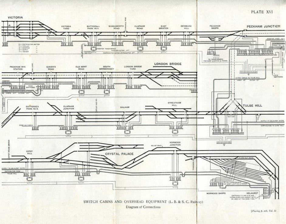
Switch Cabins & Overhead Equipment Diagram Victoria
station’s platforms 9 to 13 were electrified and at London Bridge the scheme
additionally electrified platforms 16 & 17; platforms 19 to 22 already
having been electrified under the South London ‘AC’ scheme. In
those days Peckham Rye, Queens Road, Old Kent Road & Hatcham (closed 1st
January 1917 never to reopen – possibly the first electrified mainline station
to close) and South Bermondsey all had side platforms. Note
electrification of the line up from Tulse Hill to
Peckham Rye along with the centre road
through to London Bridge Yard thence into London Bridge Station. At
Clapham Junction there was a turn-back facility in platform 18 & 19 (inc.
Pigs Hill) thence four-track electrification to Balham. The Down Siding at
Gipsy Hill was also electrified. There
was extensive electrification at Crystal Palace including on the Sydenham
line to permit access to the centre sidings between platforms 3 & 4. Into
Norwood Junction the Relief Road was electrified. Selhurst
depot had ten roads electrified and even today roads 7 to 10 are still called
the ‘AC sidings’. This electrification scheme
terminated just beyond Selhurst station to allow reversals into the
depot. |
Overhead Line Extensions
Overhead equipment for these extensions was similar to that used
on the South London lines, though of slightly lighter construction. However,
there was a greater variety of supporting structures owing to various lineside
constraints. In the tunnels at Leigham Court
(Streatham Hill), Crystal Palace and Knights Hill (Tulse
Hill) steel beams were let into the tunnel crowns and the insulators placed on
these. Some section where the track was single (the spurs between Norwood Jct.
and Bromley Jct.) used a simple pole and arm support.
Between Pouparts Jct. and Clapham Jct.
it was not possible to find space for overhead supports between the LBSCR Main
lines and the LSWR Local lines so this section had supports cantilevered out
from uprights alongside the LBSCR Down Local line. These supports were extended
across all four LBSCR tracks so that future wiring of the Main lines could be
carried out easily if required. Sufficient space was left between the uprights
of these gantries to allow a possible fifth road to be laid through them if
widening of the section became necessary.
The centre line between Peckham Rye and London Bridge was also
electrified as part of this scheme along with two further platforms at London
Bridge (16 & 17). Power supply for these lines was again taken from the
Deptford generating station of the London Electric Supply Corporation and large
distribution cabins were built at both Peckham Rye and Tulse
Hill. The switch cabins were spaced at greater distances than those on the
original South London scheme.
Electric Services
Work on these extensions proceeded quickly and the line from
Victoria to Crystal Palace via Streatham Hill was first worked electrically on
12th May 1911, this being the first day of a Festival of Empire
exhibition at Crystal Palace. Services between Peckham Rye and Streatham
Hill/West Norwood were planned to commence from 1st June 1912,
the delay being due to the electricity supply company having to install more
generating capacity to cope with the increased demand, however electric trains
actually commenced from 1st March 1912 owing to a coal shortage
following a miners strike, with the full service
commencing in June.
Initial weekday train services over the new lines consisted of a
twenty-minute frequency from Victoria to Crystal Palace from 7am to 8am, then
stepping-up to ¼ hourly until 4pm, five trains per hour until 6pm, reverting to
¼ hourly until 9pm and every 20 minutes until the last train at midnight.
When the lines via Tulse Hill opened,
a ¼ hourly service operated from London Bridge to Crystal Palace from 9am to
11am, then reducing to every 20 minutes until the last at 11 55pm. A service
from London Bridge to Victoria via Streatham Hill operated every 20 minutes
until 9 40am, then reducing to hourly until about 4pm when the 20-minute
frequency resumed until 8 8pm when the trains went back to about hourly. During
the middle part of the day some of the hourly London Bridge to Victoria trains
terminated at either Streatham Hill or Clapham Jct.
‘CP’ Rolling
Stock
Rolling stock for the new services was again contracted to the
Metropolitan Amalgamated Carriage & Wagon Co Ltd (MAC&W) of Birmingham.
Thirty new three-coach trains were needed for the service and therefore thirty
motor brake thirds and thirty driving trailer composites were ordered from
MAC&W whilst Lancing works was instructed to build a further twenty-six
driving trailer composites. Owing to some tight clearances in Crystal Palace
tunnel, the overall dimensions of these vehicles was restricted to bodies
8' 0" wide and 54' 0" long.
These coaches were built much more to LBSCR standards than the
South London line stock, all accommodation being in compartments (no side
corridors). Experience gained with the South London stock led to these trains
being more flexible in operation, all vehicles having a driving cab at one end.
There were fewer driving trailers than needed to make-up thirty complete
trains, so formations constantly varied as more motor coaches were out of
traffic for maintenance than trailer coaches.
All coaches were built on 54' underframes with bogie centres at
37', those of the motor coaches having the same style of heavy side girders as
the SL units, whilst trailers had much lighter truss rods. All coaches were
fitted with conventional buffers and screw couplings at each end. Bodies again
had aluminium sheeting covering the roofs, sides and ends as a precaution
against stray currents from the overhead equipment.
Bodysides had wooden beading dividing the panelling with two
horizontal bands beneath the window line. Within this area, the vehicle
numbers, compartment class (in words) and LBSCR lettering was displayed in gold
letters. The vehicles were all painted in umber brown with yellow & black
lining picking out the panelling.
Cab ends were quite plain, basically being a standard coach end
with two large observation windows added. They had a similar arrangement to the
SL units with an electric white light which could be covered by a red glass on
a pivoting horizontal rod to provide head and tail indications. Between the cab
windows a headcode panel was fitted into which an enamel plate displaying the
required headcode could be clipped. These were illuminated from above by
electric lamps hidden under a sloping hood. A whistle was fitted on the
nearside of the driver's window.
Similar air hose connections to the SL stock were placed low
down on the cab front close to the drawhook, three
hoses for train pipe, main reservoir pipe & bow air systems. Jumper sockets
were placed on the headstock, loose jumpers being used to connect these to adjacent vehicles when the cab was marshalled
intermediately within a train.
Bodysides had a doorway into each compartment with the usual
droplight within it, each compartment also having two ¼ light windows, one each
side of the door. Each door had a ventilator above the droplight, those in
smoking compartments having the vents at each end whilst those in non-smoking
compartments had the vent along the lower edge. Internally the compartments
were less ornate than those of the SL stock but still quite comfortable. First-class
had a blue cloth upholstery whilst thirds had a red/black repp
material. First-class seated four aside whilst thirds seated five aside. Each
compartment had two electric lamps, and there were advert frames placed above
the seats and below the luggage racks. Some compartments later had enamel
adverts fixed to the inside of the doors below the droplights.
Overall, each CP 3-car train seated 48 first and 170 third and
weighed 99 tons 6 cwt and was 172' 9" long.
Motor Coaches
Motor coaches consisted of a cab and brakevan
area 11' 6" long, this having a double opening door on each side, the
driver using these doors. Forward of these doors at the end of the bodyside
there was a droplight window, the same size as those of normal doorway ones,
though not fitted within a door, this for use of the driver. The driver
operated from a cubicle in the front nearside corner of the brakevan
area and there was an HT equipment cupboard below the offside observation
window.
Beyond the brakevan area there were 7
third class compartments, each 5' 11" wide. The roof was again
flattened above the brakevan and partly over the
first passenger compartment to allow space for the bow collectors to be mounted
above. Equipment below the underframes was very similar to that on the SL units
although at 150hp the motors were more powerful; these again being from Winter‑Eichberg. These coaches were 57' 7" long over buffers
and weighed 51 tons 6 cwt and seated 70 third. Their LBSCR diagram
number was 282.
Driving Trailer Composites
Driving trailer composites consisted of a small driver's cab
4' 0½" wide, entered from either side via a standard door with
droplight, there being no other side window to the cab. Behind this were three
first class compartments 6' 6¾" wide and five third class
compartments each 5' 10¼" wide. They weighed 24 tons and seated
24 first and 50 third. Their LBSCR diagram number was 283.
Train Formations
When first introduced the trains were formed with the motor
coach at one end of two trailers, but operating experience soon saw this
altered to having the motor coach in the centre with a driving trailer on each
end. Many peak hour trains were made up to six coaches using two 3-car
formations, and a few later ran as eight coaches with a six-car train having a
further motor coach and trailer added to one end. These trains were maintained
at the new Selhurst depot with some heavier work undertaken at Peckham Rye
repair shops. Body overhauls were carried out at Lancing works.
Further coaches of both types were added to the fleet quite
quickly (possibly as a result of the late alteration of plans to extend the
electrification scheme) and a further four motor coaches and four trailers were
constructed during 1912 by Metropolitan Carriage, Wagon & Finance Co. Ltd
(the new name for the original builders) again at Saltley.
Lancing Works built a further eight driving trailer composites (in two batches
of four with the first delivered by June 1913, the second delivered by the end
of 1913). Operation of the new trains was a success and traffic quickly grew by
as much as 70%.
The LBSCR provided ‘Stopping Marks’ on white enamel plates with
blue figures showing 2, 3, 5, 6 etc. as appropriate to indicate to drivers
where to pull-up at each station, and ‘Coasting Marks’ consisting of a blue
plate with a white cross were located (usually on an overhead support) on the
approach to stations to show when power should be shut off and the train
allowed to coast. These arrangements were also spread to the South London line.
War Years
During the First World War the electrified services suffered
some curtailments, the Sunday trains from London Bridge to Crystal Palace being
withdrawn and North Dulwich station closed on that day. Service patterns were
adjusted and although basic frequencies remained unchanged the services did not
run to a ‘clockface’ regular interval pattern.
The onset of war also stopped progress with the next phase of
the LBSCR's extension of electrification which included the lines from London
Bridge to Norwood Jct. via Forest Hill and the Sydenham Spur to Crystal Palace,
the lines from Balham to Cheam via both Mitcham Jct. and Norbury and the lines
from Selhurst /Norwood Jct. to Coulsdon North.
However, a number of driving trailer vehicles for use on these
lines had been authorised for construction at Lancing and work on these had
commenced. These were very similar to those produced for the CP stock, the
difference being that they included four first and four third class
compartments. Two of these coaches were therefore allocated to the CP fleet,
these coaches seating 32 first and 40 third, altering the capacity of any unit
in which they were formed to 56 first and 160 third.
Southern Railway
After the war, much of the further extension of the
electrification scheme was implemented by the Southern Railway though it only
had a short life as the SR had very early on decided to standardise on the ‘750v’
DC Third Rail system of electrification.
These extensions (the Coulsdon & Wallington scheme)
completed the final expansion of the LBSCR's overhead system and the extra
stock allocated to work it became known as the CW (Coulsdon & Wallington)
stock. The two CW driving trailers earlier allocated to the CP fleet however
remained working on these routes. Once the extensions had been completed (in
1925) some of the CP stock could be found working further afield, they
certainly worked to East Croydon, though they remained basically on their
original services.
From 1924, the CP fleet was renumbered into a new series by the
SR as vehicles were overhauled at Lancing works. At this time, they were also
repainted green and the new livery also changed the location of the coach
numbers, now being placed much higher up the bodyside, and figures appeared on
the lower panels of the doors to denote the class designation of that
compartment. However, not all vehicles were dealt with before the CP fleet
began to be withdrawn, this taking place during the latter part of 1928 and all
were out of service by mid-1929, as their routes were converted to DC
operation.
Conversion of ‘CP’ stock to DC Operation
All the coaches were then stripped of various items of AC
equipment at Peckham Rye and then reused in various ways as part of the
expanding fleet of DC electric units.
The motor brake thirds were converted at Lancing into trailer
thirds. The bodies remained on their original girder trussed underframes, the
former cab and brakevan area being removed and
replaced with two further third-class compartments, making these vehicles into
54' long 9-compartment coaches and they were used in trailer units 1168 ‑ 1187.
The driving trailer composites were converted in three different
ways, 14 of them becoming motor brake composites, this involving a new cab and brakevan being added to the former third-class end of the
coach, one of the original third-class compartments being replaced during this
alteration. The former cab at the other end was removed. In this form they then
had four third and three first compartments.
Conversion work took place at both Ashford and Eastleigh and the
altered bodies were removed from their 54' underframes and these were then
lengthened to 62' 0" and the bodies replaced on them, though they did
not go back onto their original frame, seven going onto new Lancing built
underframes. These new motor coaches were then formed into units 1717 ‑ 1727
and 1737 ‑ 1739.
A further two driving trailer composites were altered to 54'
trailer thirds at Lancing with little alteration to the bodies other than
downgrading the former first-class compartments to third and converting the
former cab into a coupe compartment seating 5. These 8½ compartment coaches
were then formed into trailer units 1182 and 1183.
The remaining 52 driving trailer composites were rebuilt as
62' 0" trailer composites, again the work was split between Ashford
and Eastleigh. Bodies were removed from their underframes which were then
lengthened to 62' 0” and the rebuilt bodies replaced onto them, again not
onto their original frames. Body alterations involved replacing the original
cab with a further first-class compartment and the addition of a further third-class
compartment at the other end. In this form they now had four first and six
third compartments and were included in new DC units 1717 ‑ 1768.
The two odd CW driving trailer composites used as part of the CP
fleet since 1914 were altered as 54' long trailer thirds with the former cab
being converted into a coupe compartment seating 5 and the four first class
compartments downgraded to third. These two coaches were then included in
trailer units 1184 and 1185, conversion work took place at Lancing.
The following lists show details of the CP fleet, with coaches
listed in their original number order. Details of builder, new date and
subsequent SR ‘AC’ number with date of renumbering (where appropriate) are
shown along with the date of conversion to ‘DC’, the works responsible for the
conversion, their new numbers, new unit and type of vehicle conversion. Nearly
all the DTCs had their bodies split from the underframes whilst the frames were
lengthened, they did not go back onto their original frames and the new number
of the body is shown above the number of the vehicle that the underframe was
used under. The ‘new’ date of coaches is as reported by the LBSCR accounting
system which recorded half-yearly (June & December); the actual build dates
would have been more spread.
|
CP Motor Brake Thirds |
|||||||||
|
Coach No. |
Built |
Date |
SR ‘AC’ No. |
Date Renum. |
Date Rebuilt |
Works |
SR ‘DC’ No. |
Unit |
Type |
|
3231 |
MACW |
1911 |
8567 |
Jul-24 |
Jul-30 |
LANC |
9294 |
1187 |
TT |
|
3232 |
MACW |
1911 |
8568 |
Sep-26 |
Aug-29 |
LANC |
9265 |
1172 |
TT |
|
3233 |
MACW |
1911 |
8569 |
Dec-25 |
Jan-30 |
LANC |
9280 |
1180 |
TT |
|
3234 |
MACW |
1911 |
8570 |
May-26 |
Aug-29 |
LANC |
9267 |
1173 |
TT |
|
3235 |
MACW |
1911 |
8571 |
Jan-28 |
Mar-30 |
LANC |
9291 |
1185 |
TT |
|
3236 |
MACW |
1911 |
8572 |
Jan-27 |
Jul-29 |
LANC |
9259 |
1169 |
TT |
|
3237 |
MACW |
1911 |
8573 |
Dec-24 |
Jul-29 |
LANC |
9262 |
1171 |
TT |
|
3238 |
MACW |
1911 |
8574 |
Mar-25 |
Jul-30 |
LANC |
9295 |
1187 |
TT |
|
3239 |
MACW |
1911 |
8475 |
Mar-27 |
Aug-29 |
LANC |
9269 |
1174 |
TT |
|
3240 |
MACW |
1911 |
8476 |
Sep-26 |
Sep-29 |
LANC |
9275 |
1177 |
TT |
|
3241 |
MACW |
1911 |
8477 |
Dec-24 |
Aug-29 |
LANC |
9271 |
1175 |
TT |
|
3242 |
MACW |
1911 |
8478 |
May-24 |
Feb-30 |
LANC |
9287 |
1183 |
TT |
|
3243 |
MACW |
1911 |
8579 |
Dec-25 |
Jan-30 |
LANC |
9278 |
1179 |
TT |
|
3244 |
MACW |
1911 |
8580 |
May-26 |
Jul-29 |
LANC |
9260 |
1170 |
TT |
|
3245 |
MACW |
1911 |
8581 |
Jun-27 |
Jul-29 |
LANC |
9263 |
1171 |
TT |
|
3246 |
MACW |
1911 |
(8582) |
- |
Jul-29 |
LANC |
9256 |
1168 |
TT |
|
3247 |
MACW |
1911 |
8583 |
Sep-25 |
Feb-30 |
LANC |
9285 |
1182 |
TT |
|
3248 |
MACW |
1911 |
8584 |
Jun-27 |
Aug-29 |
LANC |
9266 |
1173 |
TT |
|
3240 |
MACW |
1911 |
8585 |
Sep-27 |
Jul-29 |
LANC |
9261 |
1170 |
TT |
|
3250 |
MACW |
1911 |
8586 |
Oct-24 |
Sep-29 |
LANC |
9272 |
1176 |
TT |
|
3251 |
MACW |
1911 |
8587 |
Sep-27 |
Feb-30 |
LANC |
9289 |
1184 |
TT |
|
3252 |
MACW |
1911 |
8588 |
May-24 |
Aug-29 |
LANC |
9270 |
1175 |
TT |
|
3253 |
MACW |
1911 |
8589 |
Oct-24 |
Sep-29 |
LANC |
9273 |
1176 |
TT |
|
3254 |
MACW |
1911 |
8590 |
Jan-27 |
Sep-29 |
LANC |
9276 |
1178 |
TT |
|
3255 |
MACW |
1911 |
8591 |
Jun-25 |
Sep-29 |
LANC |
9277 |
1178 |
TT |
|
3256 |
MACW |
1911 |
8592 |
Jan-24 |
Aug-29 |
LANC |
9268 |
1174 |
TT |
|
3257 |
MACW |
1911 |
8593 |
Jun-25 |
Aug-29 |
LANC |
9264 |
1172 |
TT |
|
3258 |
MACW |
1911 |
8594 |
Oct-25 |
Jul-29 |
LANC |
9258 |
1169 |
TT |
|
3259 |
MACW |
1911 |
8595 |
Jul-24 |
Sep-29 |
LANC |
9274 |
1177 |
TT |
|
3260 |
MACW |
1911 |
(8596) |
- |
Jan-30 |
LANC |
9281 |
1180 |
TT |
|
3261 |
MCWF |
1912 |
8597 |
Apr-27 |
Jul-29 |
LANC |
9257 |
1168 |
TT |
|
3262 |
MCWF |
1912 |
8598 |
Jan-24 |
Jan-30 |
LANC |
9279 |
1179 |
TT |
|
3263 |
MCWF |
1912 |
8599 |
Jan-28 |
Feb-30 |
LANC |
9283 |
1181 |
TT |
|
3264 |
MCWF |
1912 |
8600 |
Mar-25 |
Mar-30 |
LANC |
9293 |
1186 |
TT |
|
CP Driving Trailer Composites |
|||||||||
|
Coach No. |
Built |
Date |
SR ‘AC’ No. |
Date Renum. |
Date Rebuilt |
Works |
SR ‘DC’ No. |
Unit |
Type |
|
4001 |
MACW |
Jun-11 |
9825 |
Sep-25 |
Aug-29 |
ELGH |
9749 |
1749 |
TC |
|
4002 |
MACW |
Jun-11 |
9826 |
Sep-25 |
Jul-29 |
AFD |
9732 |
1732 |
TC |
|
4003 |
MACW |
Jun-11 |
9827 |
Feb-25 |
22-Mar-30 |
AFD |
9476 |
1765 |
TC |
|
4004 |
MACW |
Jun-11 |
9828 |
Apr-25 |
Jun-29 |
ELGH |
9742 |
1742 |
TC |
|
4005 |
MACW |
1911 |
9829 |
Sep-26 |
Jun-29 |
ELGH |
8874 |
1739 |
MBC |
|
4006 |
MACW |
Jun-11 |
9830 |
May-24 |
Jan-29 |
AFD |
9719 |
1719 |
TC |
|
4007 |
MACW |
Jun-11 |
9831 |
Jul-24 |
Feb-30 |
AFD |
9468 |
1757 |
TC |
|
4008 |
MACW |
Jun-11 |
9832 |
Jan-24 |
Jan-29 |
AFD |
9717 |
1717 |
TC |
|
4009 |
MACW |
Jun-11 |
9833 |
Oct-25 |
Jun-29 |
AFD |
9726 |
1726 |
TC |
|
4010 |
MACW |
Jun-11 |
9834 |
Jun-27 |
Sep=29 |
AFD |
9730 |
1730 |
TC |
|
4011 |
MACW |
Jun-11 |
9835 |
Jan-24 |
Feb-29 |
AFD |
9720 |
1720 |
TC |
|
4012 |
MACW |
1911 |
9836 |
Sep-26 |
Jun-29 |
ELGH |
8873 |
1738 |
MBC |
|
4013 |
MACW |
Jun-11 |
9837 |
Sep-26 |
May-29 |
AFD |
8598 |
1724 |
MBC |
|
4014 |
MACW |
Jun-11 |
9838 |
Feb-24 |
1-Jan-30 |
AFD |
9462 |
1751 |
TC |
|
4015 |
MACW |
Jun-11 |
9839 |
Sep-26 |
Jun-29 |
ELGH |
9738 |
1738 |
TC |
|
4016 |
MACW |
Jun-11 |
9840 |
Jun-27 |
5-Apr-30 |
AFD |
9478 |
1767 |
TC |
|
4017 |
MACW |
1911 |
9841 |
Apr-27 |
Feb-30 |
LANC |
9284 |
1182 |
TT |
|
4018 |
MACW |
Jun-11 |
9842 |
Mar-25 |
May-29 |
AFD |
9725 |
1725 |
TC |
|
4019 |
MACW |
Jun-11 |
9843 |
Sep-24 |
Aug-29 |
AFD |
9736 |
1736 |
TC |
|
4020 |
MACW |
Jun-11 |
9844 |
Dec-24 |
Feb-30 |
AFD |
9463 |
1752 |
TC |
|
4021 |
MACW |
Jun-11 |
9845 |
Sep-27 |
Jun-29 |
AFD |
9737 |
1737 |
TC |
|
4022 |
MACW |
Jun-11 |
(9846) |
- |
Feb-29 |
AFD |
8856 |
1721 |
MBC |
|
4023 |
MACW |
1911 |
9847 |
Apr-27 |
Jun-29 |
AFD |
8862 |
1727 |
MBC |
|
4024 |
MACW |
Jun-11 |
9848 |
Jun-27 |
May-29 |
AFD |
9724 |
1724 |
TC |
|
4025 |
MACW |
1911 |
9849 |
Oct-27 |
Jun-29 |
AFD |
8861 |
1726 |
MBC |
|
4026 |
MACW |
Jun-11 |
9850 |
Sep-27 |
Jul-29 |
ELGH |
9743 |
1743 |
TC |
|
4027 |
MACW |
Jun-11 |
9851 |
Oct-27 |
Jun-29 |
AFD |
9727 |
1727 |
TC |
|
4028 |
MACW |
Jun-11 |
9852 |
Jan-28 |
Feb-30 |
AFD |
9470 |
1759 |
TC |
|
4029 |
MACW |
Jun-11 |
9853 |
Apr-26 |
Jun-29 |
AFD |
9728 |
1728 |
TC |
|
4030 |
MACW |
Jun-11 |
9854 |
Jan-24 |
Feb-29 |
AFD |
8854 |
1719 |
MBC |
|
4032 |
LANC |
Jun-11 |
9855 |
Dec-25 |
Aug-29 |
AFD |
9734 |
1734 |
TC |
|
4032 |
LANC |
1911 |
9856 |
Jun-Jan-28 |
Feb-30 |
LANC |
9286 |
1183 |
TT |
|
4033 |
LANC |
Jun-11 |
9857 |
Jan-27 |
May-29 |
AFD |
8860 |
1725 |
MBC |
|
4034 |
LANC |
Jun-11 |
(9858) |
- |
Feb-29 |
AFD |
9721 |
1721 |
TC |
|
4035 |
LANC |
Jun-11 |
9859 |
Jan-28 |
1-Jan-30 |
AFD |
9467 |
1756 |
TC |
|
4036 |
LANC |
Jun-11 |
9860 |
Jan-24 |
Jan-29 |
AFD |
8853 |
1718 |
MBC |
|
4037 |
LANC |
Jun-11 |
9861 |
Feb-25 |
Jun-29 |
AFD |
9729 |
1729 |
TC |
|
4038 |
LANC |
Jun-11 |
9862 |
Jul-24 |
Feb-30 |
AFD |
9469 |
1758 |
TC |
|
4039 |
LANC |
Jun-11 |
9863 |
Jan-27 |
1-Jan-30 |
AFD |
9461 |
1750 |
TC |
|
4040 |
LANC |
Jun-11 |
9864 |
Dec-24 |
1-Jan-30 |
AFD |
9466 |
1755 |
TC |
|
4041 |
LANC |
Jun-11 |
9865 |
Jan-24 |
Feb-29 |
AFD |
9723 |
1723 |
TC |
|
4042 |
LANC |
Jun-11 |
9866 |
Feb-25 |
Sep-29 |
AFD |
9731 |
1731 |
TC |
|
4043 |
LANC |
Jun-11 |
9867 |
Jul-24 |
Jun-29 |
ELGH |
9741 |
1741 |
TC |
|
4044 |
LANC |
Jun-11 |
9868 |
Dec-24 |
Feb-30 |
AFD |
9464 |
1753 |
TC |
|
4045 |
LANC |
Jun-11 |
9869 |
Sep-25 |
1-Jan-30 |
AFD |
9465 |
1754 |
TC |
|
4046 |
LANC |
Jun-11 |
9870 |
Jun-27 |
Mar-30 |
AFD |
9473 |
1762 |
TC |
|
4047 |
LANC |
Jun-11 |
9871 |
Jun-25 |
Aug-29 |
ELGH |
9747 |
1747 |
TC |
|
4048 |
LANC |
Jun-11 |
9872 |
May-24 |
Jan-29 |
AFD |
9718 |
1718 |
TC |
|
4049 |
LANC |
Jun-11 |
9873 |
Jun-25 |
12-Apr-30 |
AFD |
9479 |
1768 |
TC |
|
4050 |
LANC |
1911 |
9874 |
Jan-24 |
Feb-29 |
AFD |
8855 |
1720 |
MBC |
|
4051 |
LANC |
Jun-11 |
9875 |
Jan-27 |
Mar-30 |
AFD |
9474 |
1763 |
TC |
|
4052 |
LANC |
Jun-11 |
9876 |
Jun-25 |
29-Mar-30 |
AFD |
9477 |
1766 |
TC |
|
4053 |
LANC |
Jun-11 |
9877 |
Apr-26 |
Aug-29 |
ELGH |
9748 |
1748 |
TC |
|
4055 |
LANC |
Jun-11 |
9878 |
Jan-27 |
Jul-29 |
AFD |
9733 |
1733 |
TC |
|
4056 |
LANC |
Jun-11 |
(9879) |
- |
Feb-29 |
AFD |
9722 |
1722 |
TC |
|
4057 |
LANC |
Jun-11 |
(9880) |
- |
Feb-29 |
AFD |
8858 |
1723 |
MBC |
|
4061 |
MCWF |
1912 |
9881 |
Oct-24 |
Jun-29 |
ELGH |
8872 |
1737 |
MBC |
|
4062 |
MCWF |
Dec-12 |
9882 |
Jul-24 |
Aug-29 |
AFD |
9735 |
1735 |
TC |
|
4063 |
MCWF |
Dec-12 |
9883 |
May-24 |
Feb-29 |
AFD |
8857 |
1722 |
MBC |
|
4064 |
MCWF |
Dec-12 |
9884 |
Oct-24 |
Jun-29 |
ELGH |
9739 |
1739 |
TC |
|
4065 |
LANC |
Jun-13 |
9885 |
Jan-26 |
Feb-30 |
AFD |
9471 |
1760 |
TC |
|
4066 |
LANC |
Jun-13 |
9886 |
Dec-25 |
Feb-30 |
AFD |
9472 |
1761 |
TC |
|
4067 |
LANC |
Jun-13 |
9887 |
May-26 |
Jul-29 |
ELGH |
9744 |
1744 |
TC |
|
4068 |
LANC |
Jun-13 |
9888 |
Oct-25 |
15-Mar-30 |
AFD |
9475 |
1764 |
TC |
|
4069 |
LANC |
Dec-13 |
9889 |
Dec-25 |
Aug-29 |
ELGH |
9746 |
1746 |
TC |
|
4070 |
LANC |
Dec-13 |
9890 |
Jan-28 |
Aug-29 |
ELGH |
9745 |
1745 |
TC |
|
4071 |
LANC |
Dec-13 |
9891 |
Apr-26 |
Jun-29 |
ELGH |
9740 |
1740 |
TC |
|
4072 |
LANC |
Dec-13 |
9892 |
May-24 |
Jan-29 |
AFD |
8852 |
1717 |
MBC |
|
CP Driving Trailer Composites |
|||||||||
|
Coach No. |
Built |
Date |
SR ‘AC’ No. |
Date Renum. |
Date Rebuilt |
Works |
SR ‘DC’ No. |
Unit |
Type |
|
4084 |
LANC |
1914 |
9893 |
Apr-27 |
Feb-30 |
LANC |
9288 |
1184 |
TT |
|
4085 |
LANC |
1914 |
9894 |
Apr-27 |
Feb-30 |
LANC |
9290 |
1185 |
TT |
|
Thanks go to research
author John Atkinson, webpage author, editorial and additional information from
C.Watts along with the many photographers listed
below their images. |
|
In memory of J.F. Watts
and his childhood recollections of the ‘CP’ rolling stock “hissing through
Crystal Palace with their great big bow-collectors”. |
ALL TEXT AND PHOTOGRAPHS
ARE COPYRIGHT