BR British Rail Crimson & Cream
Crimson and Cream Crimson Cream Blood & Custard Blood Custard Blood and
Custard BR British Rail Crimson & Cream Crimson and Cream Crimson Cream
Blood & Custard Blood Custard Blood and Custard BR British Rail Crimson
& Cream Crimson and Cream Crimson Cream Blood & Custard Blood Custard
Blood and Custard
London,
Brighton & South Coast Railway
South London ‘SL’
‘Elevated
Electric’ AC stock
|
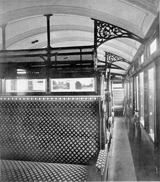
Interior of a former ‘AC’ SL
Motorcoach |
Around the turn of the century, the London, Brighton & South
Coast Railway (LBSCR) were concerned about falling traffic receipts in the
suburban area and also wished to make economies in the costs of working their
system. So, they began investigations into the feasibility of working their
trains electrically. Electric operation of trains was now becoming quite
practical and was indeed already in operation on a number of railways abroad
and the LSWR had commenced limited electric operation in 1898 in the Waterloo
& City Railway tube line.
The construction of further electrified tube railways in London
and the parallel electrification of some competing tramway routes also spurred
these investigations by the LBSCR and the company obtained an Act of Parliament
in July 1903 to enable it to electrify parts of its system. Philip Dawson was
retained as a consulting electrical engineer to investigate the most suitable
system and from an early stage it was agreed that the system chosen should be
suitable for use on possible future extensions of the system beyond the
suburban area. Dawson took into account an earlier report to the LBSCR board
presented in 1902 by the Chief Engineer which pointed out a number of
disadvantages of the third rail system for the LBSCR network and presented a
report to the board in July 1904 recommending the adoption of a single‑phase
alternating current system at nominal 6,700 volts using overhead contact wire.
The system was envisaged as suitable for the whole suburban network and with
the possibility of later extensions should this be required.
Dawson was instructed to prepare plans for electrification of
the lines between Battersea Park and Peckham Rye via the South London line and
contracts were let in April 1905, awarded to the Allgemeine Elektricitats-Gesellschaft
(AEG) of Berlin; this company sub‑contracting the overhead line work to
Messrs R. W. Blackwell & Company of London, who in turn sub-contracted
further with British Thomson‑Houston Co providing switchgear and Johnson
& Philips also Siemens Bros providing cabling. Soon after these contracts
were let, the LBSCR decided to extend the electrification scheme from Peckham
Rye into London Bridge and from Battersea Park into Victoria so that the whole
South London line route was covered, and further contracts were let to cover
these extensions in March 1906. The rolling stock provision for the line was
awarded to the Metropolitan Amalgamated Carriage & Wagon Company of
Birmingham.
The Overhead
Power for the system was obtained from the London Electric
Supply Corporation's generating station at Deptford and supplied at nominal
6,700 volts, 25 hertz via cables direct to a switch room at Queens Road,
Peckham and a distribution room at Peckham Rye. Power was then distributed via
lineside cables to switch cabins located at each station which supplied the
overhead equipment. Wherever possible the current supply arrangements allowed
one line to be isolated without having to isolate the adjacent track. The
overhead lines were suspended at a contact height of 16' above rail level,
though this was reduced under certain low bridges to 13' 9" (where
there were ‘Dead’ sections) whilst in the vicinity of the platforms
at Victoria and London Bridge the height was raised to 19' 9" to give
greater clearances as staff still had to go onto carriage roofs to lamp oil lit
stock or light gas lamps in some gas lit stock.
The contact wire was suspended from two catenaries; these being
located one to each side and away from the centre line of the track to avoid
damage to the insulators from the blast of locomotive chimneys. The catenaries
were made of 12 strand galvanised steel and the droppers from these to the
contact wire were formed as a stiff ‘V’ shape and were clipped to
the contact wire by phosphor bronze clips. Droppers were spaced every 10' and
held the copper contact wire off centre above the track with alternate deviations
of 9" from the track centre line; this zig-zagging of the contact wire was
designed to prevent the wire wearing a groove into the bow collectors of the
trains.
The structures supporting the catenaries were mostly steel
lattice gantries, the catenaries passing above these structures and supported
on porcelain insulators, though there were some variations in the vicinity of
overbridges. The overhead gantries were usually spaced about 150' apart, though
some gaps were as small as 50' and the longest was 210' owing to siting
difficulties.
Minimum clearance around the contact wire was specified at
3", though 4" was normally allowed, and the loading gauge height of
the LBSCR was set at 13' 6" so the minimum height of the contact wire
had to be set at 13' 9". As a consequence, there was a need for
‘Dead’ sections with the wire at this height under five overbridges
on the electrified lines.
The Original
South London Route
The total length of single track electrified for this initial
scheme was 20½ miles, the route mileage from London Bridge to Victoria
being 8 miles, 51 chains.
At London Bridge, four platforms were electrified (numbered
19 ‑ 22 in SR days) and the two outermost South London lines
were equipped as far as Peckham Rye, the centre road (made reversible between
South Bermondsey Jct. and London Bridge as part of the electrification scheme)
remained unelectrified. From Peckham Rye to Battersea Park only the two lines
used by LBSCR trains were equipped, whilst from Battersea Park into Victoria
only the Local lines were electrified as the track layout did not allow South London
line trains to reach the Main lines.
Platforms 9 ‑ 13 at Victoria were electrified;
both the South & North sections. Precautions to cope with the current in
the event of a centenary collapse included facing platform awnings with zinc at
intermediate stations and ensuring they were well earthed. A depot to service
the new electric trains was provided at Peckham Rye where the Denmark Hill and
Tulse Hill lines diverged, and a three bay repair shop built alongside to look
after the heavier maintenance on the trains.
New Electric
Trains
The rolling stock provided for this electrification scheme
consisted of 8 number three-coach loose coupled units formed of third-class
motorcoach at each end of a first-class trailer. Second class accommodation was
not provided in the electric trains. As the South London line was mostly
carried on viaducts, there were few tight structural restrictions on the route
and the new trains took advantage of the generous loading gauge with each
vehicle being 63' 7" long and 9' 5" wide overall.
The stock was designed by Philip Dawson (for the electrical
engineering aspects) and Albert Panter (the LBSCR's carriage & wagon
foreman) for the bodywork design, though quite how much detail was specified by
Panter is questionable as the coaches when delivered had a number of features
not normally found on LBSCR carriages and may have been the result of the
builder's interpretation of some general design directives.
Some consideration was given to the new trains being fitted with
sliding doors, but the tender from the Metropolitan Amalgamated Carriage &
Wagon Company for coaches fitted with slam doors and with internal side
corridors to assist passenger circulation was the lowest and was accepted; the
coaches then being constructed at Saltley. The overall width of these vehicles
at 9’ 5” was possibly a result of considering sliding doors
with their associated door pockets and when a decision to construct them with
conventional slam doors was made the overall width was not reduced as the lack
of any restrictive clearances on the South London line meant that this was not
a problem.
Into Service
The new electric trains consisted of a Motor Brake Third at each
end sandwiching a Trailer First. The first unit was delivered in December 1908
and the first test run with the train was made on 5 January 1909 with a
publicity run for Press representatives being made in the evening of 17 January
between Battersea Park and East Brixton. The remaining units were delivered
steadily during 1909 and public services were commenced from 1 December 1909.
An earlier starting date had been planned, but there were objections from the
Postmaster‑General regarding electrical interference with his cables and
a number of other problems concerning the equipment which required
modifications, along with waiting for sufficient units to be delivered from the
builders.
The new train service provided a frequency of four trains per
hour from 7:30am until midnight (earlier trains on the line from 4:30am until 7:30am
were still steam operated to allow time for maintenance of the overhead
equipment). On Sundays trains ran at half hourly intervals from 7:15am until 11:15pm,
though there was a two-hour gap during the morning. The electric trains
completed the journey in 24 minutes, a reduction of one third on the steam
timings of 36 minutes. Each train made the round trip once per hour, requiring
four trains to maintain the timetable with two spare and two undergoing
maintenance.
Reformation
of Trains
Initial results of the electrification were very good, with
passenger levels rising from about 4 million journeys in 1908 to 7½
million in 1910. The new service was promoted by the LBSCR as the
‘Overhead Electrics’ with a range of special tickets and was well
rewarded by the increase in passenger numbers. However, it was quickly found
that the new trains had far too much provision of first class seating, insufficient
third class accommodation and were too generous for the slack hour traffic but
provided insufficient overall accommodation during the peak periods.
Therefore from 1910 the Trailer First coaches began to be
withdrawn and replaced by a Driving Trailer Composite; the units then being
reformed as two-car trains with one Motor Brake Third coupled to a Driving
Trailer Composite. These driving trailers were converted from former
bogie-block suburban coaches and were both shorter and narrower than the
motorcoaches, presenting an odd‑looking appearance as two coach units.
The first two-coach train ran in October 1910, and all the units
had been reformed as two-coaches by June 1912. As three-car sets the units had
been maintained in fixed formations and allocated the unit numbers 1E to 8E. However,
after reforming as two-car trains fixed unit formations were abandoned, indeed
only 14 Driving Trailer Composites were converted to run with the 16 Motor
Brake Thirds.
From 1912 the whole train service was operated electrically, the
basic pattern established in 1909 with ¼ hourly trains on weekdays and
½ hourly on Sundays being maintained. Trains were now variously
formed of two, four or six coaches depending on the traffic levels, though some
trains had been formed with two units when they were still in three car form.
The displaced Trailer Firsts were stored until 1913 when they were converted at
Lancing Works into steam-hauled vehicles for use on the Brighton line.
Wartime
The service suffered some cuts during the 1914-18 war and both
South Bermondsey and Old Kent Road stations were closed from January 1917,
South Bermondsey subsequently reopening in May 1919. However, Old Kent Road was
never reopened and the station demolished in April 1925. East Brixton station
also closed on Sundays from this time and did not have Sunday services restored
until July 1925. The two-car South London units continued to work the route for
the remainder of the existence of the LBSCR and remained working on this line
in the early SR years until displaced in June 1928 when the line was converted
to DC operation. The coaches (with one exception) were all renumbered by the SR
into a new series during body overhauls at Lancing Works. They were also
repainted into SR green livery at this time now having the coach numbers placed
much higher on the bodysides and the class designation of the compartments now
shown by a figure lower on the door panels.
Withdrawal
of AC units
After displacement by DC trains the withdrawn SL units were
stripped of their AC equipment at Peckham Rye and the Driving Trailers were
further converted (both at Ashford (11) and Eastleigh (3)) their bodies being
remounted onto 62' 0" underframes and new cabs built on, seven of
these frames being lengthened former ‘AC’ stock frames from ex. CP
and CW vehicles, whilst seven were new.
The fourteen displaced 48' frames were not suitable for
lengthening and were scrapped. All became Motor Brake Thirds for further new DC
units nos.1717 ‑ 1727 and 1737 ‑ 1739 required
for the electrification of the Central Section lines. The Motor Brake Third
coaches were also converted to DC operation, half of them becoming Motor Brake
Thirds, the other half becoming Driving Trailer Brake Composites; these
vehicles then being paired as 8 two-car units and again returned to operate on
the South London line once more as 2SL units nos.1901 ‑ 1908.
‘SL’ Rolling Stock
The coaches built for the South London line electric units were
built to maximise the use of the generous loading gauge on this line with each
vehicle being 60' 0" long of bodywork (63' 7" over buffers)
and 9' 0" wide (9' 5" overall over commode handles). All
vehicles were mounted onto steel underframes, these had quite deep
strengthening girders between the bogies giving these units (and other
subsequent ‘AC’ design units) a distinctive appearance.
The South London line units in their original form were
190' 9" long, weighed 138 tons and seated 56 first and 132 third.
Bogie centres were at 41' 0" and all bogies were of
8' 0" wheelbase with pressed steel frames, wheel diameter was
3' 7½". Bodies were of wooden framed construction with
aluminium sheeting used for bodysides, roofs and ends; this being specified as
part of the precautions to deal with stray current in event of breakage of the
overhead equipment and parts coming into contact with the train.
Each seating compartment had a door on both sides, doors having
the usual droplight within them and having a ¼ light window on each
side. Above each ¼ light window a further much smaller rectangular
window was provided, these could be partly opened by hinging outwards from one
end. A fluted air ventilator with the vent along the bottom edge was provided
above each door droplight whilst there were other similar ones in the luggage
van doors, above the Driver's droplight and one in the bodyside between the luggage
doors and the first passenger ¼ light.
The roof above the Driver's cab and Guard's Compartment was
flattened down to allow space for the bow collectors to be mounted on it, the
roof then rose to a normal profile above the first passenger compartment.
Transverse wooden slats were fitted to the roofs above each passenger doorway,
again to give added protection in the event of any broken overhead equipment
coming into contact with the train.
Two lines of panel beading ran along the waist of the coaches,
panel corners being square and the coaches were finished in umber brown livery
on the lower panels with cream upper panels (specified as ivory white) above.
Panels were picked-out with gold lining whilst the class of compartment was
also indicated in words in gold lettering on each door in the space between the
lines of panel beading. Also in this panel space the word ‘Guard’
appeared on one of the luggage van doors whilst the coach number appeared
twice, once in the space between the luggage doors and the first passenger
door, and again between the sixth & seventh passenger doors, and the legend
LB&SCR also appeared twice, between the second/third and fourth/fifth
passenger doors.
Underframes and coach ends (including cab ends) were black and
coach roofs were white. Internally these coaches were well appointed. Each
passenger compartment had access to a side corridor; this was an
‘open’ corridor in that there was no partition or sliding door
dividing the corridor from the compartment. Transverse partitions were not full
height, only extending above the seating as far as the tops of the
advertisement panels up to the level of the top of the ¼ light
windows. Above the top of these transverse partitions was fitted a double wire
mesh luggage rack, the larger upper part for luggage and parcels whilst the
smaller lower part was for umbrellas etc, these racks at their gangway ends
having ornate ironwork brackets joining them to the roof and to bodysides along
the corridor. The inner roofs had quite complex lincrusta
mouldings and each compartment had two carbon filament lamps.
First-class compartment dimensions were 6' 6"
partition‑to‑partition width whilst thirds were 6' 0".
The original upholstery in first-class was blue with a red/black pattern used
in third-class. Pull down blinds were provided above each ¼ light and
door droplight window. There was a swing door in each vehicle across the
corridor dividing the smoking and non-smoking sections of the passenger area,
in the motor coaches this door divided the coach into two groups of four
compartments whilst in the trailer it was split five & four. However, there
was no provision in the stock for any carriage heating.
As a further precaution against stray currents, the floors of
the coaches were built as a double floor with slag wool over Uralite insulating
material with aluminium sheeting being earthed to the underframe. Very early in
the lives of the units, droplight windows had two window bars fitted
horizontally across them to prevent passengers leaning out, presumably this was
the result of some tight clearances being identified somewhere on the route
with such wide coach bodies.
Motor Brake
Thirds
The Motor Brake Third coaches built for the South London line
consisted of a luggage van space at the cab end of the coach, the Driver's
cubicle being located in the nearside corner of this area and was about half
the width of the cab front. The cab front was fairly plain, being basically
flat, though there was some panel beading running vertically down the front
dividing the frontal area into six. Two large observation windows were provided
high up on the cab front, which on the nearside for use of the driver, the
other giving onto the brake van being available for use of the Guard.
An air operated whistle was mounted on the nearside of the
driver's window and below this window a horizontal bar was mounted, this could
be rotated along its length from within the cab and either exhibited a white
disc with a white light below as a head indication, or when rotated the disc
covered the light which now showed a red light through the disc which had
‘LV’ (Last Vehicle) stencilled on it to provide a tail indication.
A windscreen wiper was fitted to the driver's observation window and at buffer beam
level there were three air hose connections, one being the ‘train
pipe’ air braking connection adjacent to the ‘main reservoir’
connection, whilst the other, close to the draw hook was a connection for the
air system used to raise and lower the current collecting bows.
Conventional side buffers and a central draw hook were provided
to enable the unit to be coupled to another, or to an assisting locomotive.
Near the end of the bodywork each side was a droplight window for use of the
Driver and behind were a pair of double outward opening doors, one each side
for use of the Guard and for loading of parcel and luggage etc.
The cab and luggage van were about 14' 6" long. A full
width partition divided this luggage area from the passenger compartments.
These were unusual in layout, there being 8 compartments; each served by a side
door each side. A side corridor ran from end to end of the coach, this starting
on the offside at the brake van end and running along the first five
compartments where it changed sides and then ran along the nearside of the last
three compartments. Below the underframe items of equipment were located; from
the cab end these being the bow air reservoir, reversing switch, contactors,
resistances, air compressor, main air reservoir, main transformer and exciter
transformer.
On the flattened roof section above the cab/brakevan
was located the bow collectors. There were two of these, one laying in each
direction as they could only operate in the ‘trailing’ direction,
the relevant one therefore being raised depending on direction of travel. At
terminals, or where trains otherwise changed direction, the second bow would be
raised before the first was lowered. Bows were raised/lowered by air pressure,
there was a hand operated pump in each train which could be used to raise one
of the bows after the train had been berthed ‘off power‘. All the ancillary
equipment on the roof was live when the bows were raised and was surrounded by
a protective wire mesh basket, these being fitted shortly after the trains were
introduced, as some evidence exists of the early test runs running without
these being in place.
The bows were 5' 2" wide and had two aluminium
collector strips 3' 7¼" wide bearing onto the contact wire. A
groove between these strips was filled with a mixture of Vaseline and black
lead to give a measure of lubrication, these being found sufficient to allow
trains to run approximately 5000 - 6000 miles (about 4 - 5 weeks) without
renewal. When new, a further aluminium trailing collector, sprung loaded
against the contact wire was fitted, trailing along behind the bow, but these
were found unnecessary and soon removed.
Each motor coach was fitted with four 115hp single phase AC
motors, one driving each axle. These were supplied by AEG to a design patented
by Winter-Eichberg and were the most powerful available at that time. The
motors were compensated repulsion motors and required an exciter transformer
working in proportion to the main transformer voltage (this being varied by the
position of the driver's controller) to operate. The motors drove the wheels
with a gear ratio of 25 (pinion)/83 (gearwheel), each motor coach having two
220kw main transformers (one for each pair of motors) which turned the power
supply into traction supply at a maximum of 750v. The transformers supplied
current in incremental steps depending on the driver's control setting with an
initial voltage of 450v and other settings at 580v, 640v and 750v. A further
transformer supplied power at 300v for other items of equipment, the control
equipment, Westinghouse brake compressors and the carriage lighting. Various
items of HT equipment were mounted in a cupboard below the offside cab window,
when the doors of this cupboard were opened, the air supply to the bow was cut
off causing these to be lowered and the equipment connected to earth.
Within the unit, a main reservoir pipe ran along the train
charged to 110 lb per sq in by the compressors, the
train pipe also ran the length of the train regulated to 70 lb per sq in, whilst there was a further pipe for the bow air
system giving three flexible connections between coaches within unit. Inboard
of the buffers at cab ends were sockets to allow loose jumpers to be connected
to allow coupling in multiple to another unit.
These coaches weighed 54 tons and were to Diagram number
280. They seated 66 (five aside in the full width seats at each end of the
passenger area, and four aside in the remaining seats alongside the side
corridor), though the seating capacity was later revised upwards as each seat
was then regarded as seating one extra passenger, the new capacity now being
82, this alteration probably taking place when the units were reformed as two
coach trains.
Trailer
Firsts
The Trailer First in each unit consisted of 9 compartments each
6' 6" wide. Once again, the side corridor changed sides, this time in
the centremost compartment. The seats were divided by armrests, the full width
seats at each end seating four aside whilst those with the side corridor
alongside seated three aside giving an overall capacity of 56. Jumper cables
from the motor coaches supplied power at 300v for the coach lighting and
transmitted the control currents between the two motor coaches. These vehicles
were to Diagram number ??? and weighed 30 tons.
Reformations
From October 1910 the units began to be reformed as two-coach
trains using a newly converted Driving Trailer Composite coupled to one of the
original motor coaches. These driving trailers were converted from 7-compartment
Brake Thirds formerly used at the ends of seven coach bogie suburban block
trains built variously at either Brighton Works or by the Birmingham Railway
Carriage & Wagon Co. between 1898 and 1901.
These coaches were built on steel underframes and were 48' long
over bodywork and 8' 0" wide (8' 9" over the Guard's
duckets). They had Fox's pressed-steel bogies of 8' 0" wheelbase with
bogie centres at 32' 0" and were electrically lit from new. As they
were marshalled at the end of the sets, they had conventional buffers at the brake
van end and a centre buffer/block arrangement at the other end. They were also
fitted with air brakes. Each of the compartments was 5' 2.5/8" wide
and the brakevan was 10' 4½" long
and the overall weight was 19 tons 18cwt (those fitted with dynamos weighed 20
tons) and were to Diagram number 158.
Conversion
to Electric Stock
Conversion to electric working took place at Lancing Works, six
being done during 1910, with a further four each in 1911 and 1912. This conversion
work involved removing the brake van and adjacent third compartment and
replacing them with two first class compartments 6' 0" between
partitions. A new cab (approx. 3' 7" deep) was provided at the end of
the coach, this having a standard door with droplight each side but no other
side window. The cab end had a similar layout to that of the original motor
coaches with two large observation lights and a similar horizontal spindle rod
arrangement for the head and tail lights, though this did not extend right
across the cab front, only running about halfway from the nearside (the
arrangement on the original motor coaches was altered to be similar at about
this time).
Identical air connections and jumper sockets were fitted at
solebar level to enable these new cabs to be run intermediately within a train.
Other alterations involved fitting conventional buffing gear at the non-cab end
replacing the former centre buffer /block arrangement, and cables to carry the
300v DC current for the coach lighting and control circuits.
As converted, these coaches were now to Diagram number 281 and
weighed 20 tons 8cwt and were 51' 7" long over buffers. They now had
two first and six third-class compartments and seated 16 first and 60 third.
These coaches were outshopped in all‑over umber brown livery and the motor
coaches therefore had their cream areas painted umber to match. Being narrower
than the motor coaches, the driving trailers did not have any bars fitted over
the door droplights. They also had underframes without the distinctive heavy
side girders found on the original South London vehicles.
Overall capacity of the two car South London units was therefore
now altered to 16 first and 142 second and they now weighed 74 tons 8cwt and
were 115' 2" long overall. Most off-peak trains were now formed of
one of these units, whilst peak hour trains used three, though a few trains
were formed of four coaches using two of them. From the time of reforming, any
sort of permanent unit formations was abandoned, vehicles being coupled in
pairs as required as motor coaches were out of traffic more frequently for
maintenance than the driving trailers.
Restrictions
Owing to their dimensions, the ‘SL’ stock was
tightly route restricted, only being permitted to run on its original route.
Following further extensions of the overhead electrification, they were
permitted to run empty from Peckham Rye to Selhurst Depot via
Tulse Hill and Streatham. However, they were not permitted to pass through
either Crystal Palace or Leigham Tunnels. Special arrangements were made from
time to time for the stock to be hauled to Lancing Works for body overhauls and
repainting. All other routine maintenance and heavier mechanical work on the
running gear, motors etc was all carried out at their own depot at Peckham Rye.
Headcodes
With the extension of AC electrification to Coulsdon /Sutton in
April 1925 a system of headcodes was introduced by the Southern Railway and the
South London units were modified with a headcode plate (showing SL) fitted
between the observation windows on the cab end. Above these was a slanting
metal hood which covered lamps to provide illumination of the headcode at
night.
Displaced
Trailer Thirds
The displaced original Trailer Firsts were stored following
their removal from the electric units and during 1913 were taken to Lancing
Works. Here they were converted for steam operation involving the fitting of
steam heating and alteration of the lighting system to operate from dynamos and
batteries.
The major alteration involved the conversion of the centremost
compartment into two lavatories (side by side) so that now the side corridors
in each half of the coach (still on opposite sides in each half) now led into
these lavatories via a swing door.
Overall, these coaches now seated 50 first and were now to
Diagram number 65. They were then used on London - Brighton/Worthing main line
services (there were a number of restrictions placed on them owing to their
size). They were renumbered into the loco-hauled series as 167 ‑ 174
and were later renumbered by the SR as 7644 ‑ 7651 in 1927/8 as
they passed through Lancing Works for overhaul.
They remained in use in this form until 1930 when all were
withdrawn and again sent to Lancing for further conversion, this time more
extensively rebuilt as DC electric vehicles, four of them becoming Motor Brake
Composites whilst the other four became Driving Trailer Brake Thirds, these
vehicles then being paired to form four two-coach units for the Wimbledon ‑ West
Croydon line numbered 1909 ‑ 1912.
Original formations of South London
three-coach units
|
UNIT |
New |
MBT |
TF |
MBT |
|
1E |
Dec-08 |
3201 |
3202 |
3203 |
|
2E |
Apr-09 |
3204 |
3205 |
3206 |
|
3E |
c.Jun-09 |
3207 |
3208 |
3209 |
|
4E |
c.Jun-09 |
3210 |
3211 |
3212 |
|
5E |
c.Jun-09 |
3213 |
3214 |
3215 |
|
6E |
c.Jun-09 |
3216 |
3217 |
3218 |
|
7E |
c.Dec-09 |
3219 |
3220 |
3221 |
|
8E |
Dec-09 |
3222 |
3223 |
3224 |
|
The
‘new’ dates are official dates; it is probable that units were
actually delivered more evenly spaced. |
||||
Motor Brake
Thirds
LBSCR
Diagram No. 280, SR Diagram No 677.
|
Coach No. |
New date |
SR No. |
Renumbered |
Rebuilt
date |
New DC
date |
Unit No. |
Type No |
|
3201 |
Dec-08 |
8601 |
Feb-25 |
May-29 |
9751 |
1901 |
DTBC |
|
3203 |
Dec-08 |
8602 |
Sep-24 |
Apr-29 |
9752 |
1902 |
DTBC |
|
3204 |
Apr-09 |
- |
- |
Apr-29 |
9758 |
1908 |
DTBC |
|
3206 |
Apr-09 |
8604 |
Apr-24 |
May-29 |
8723 |
1901 |
MBT |
|
3207 |
c.Jun-09 |
8605 |
Dec-25 |
Apr-29 |
9753 |
1903 |
DTBC |
|
3209 |
c.Jun-09 |
8606 |
Aug-27 |
Apr-29 |
8724 |
1902 |
MBT |
|
3210 |
c.Jun-09 |
8607 |
Oct-25 |
Apr-29 |
9754 |
1904 |
DTBC |
|
3212 |
c.Jun-09 |
8608 |
Jun-25 |
Apr-29 |
8725 |
1903 |
MBT |
|
3213 |
c.Jun-09 |
8609 |
Mar-26 |
May-29 |
9755 |
1905 |
DTBC |
|
3215 |
c.Jun-09 |
8610 |
Jun-26 |
Apr-29 |
8726 |
1904 |
MBT |
|
3216 |
c.Jun-09 |
8611 |
Jan-27 |
May-29 |
9756 |
1906 |
DTBC |
|
3218 |
c.Jun-09 |
8612 |
Nov-24 |
May-29 |
9757 |
1907 |
DTBC |
|
3219 |
c.Dec-09 |
8613 |
Jan-24 |
May-29 |
8727 |
1905 |
MBT |
|
3221 |
c.Dec-09 |
8614 |
May-27 |
May-29 |
8728 |
1906 |
MBT |
|
3222 |
Dec-09 |
8615 |
Apr-25 |
May-29 |
8729 |
1907 |
MBT |
|
3224 |
Dec-09 |
8616 |
Jul-24 |
Apr-29 |
8730 |
1908 |
MBT |
Trailer
Firsts
LBSCR
Diagram No. ??? (later 65 when converted to loco-hauled), SR Diagram No 524.
All rebuilt
in June 1930 for DC use
|
Coach No. |
New date |
2nd
LBSCR No. |
SR No. |
Renumbered |
New DC
date |
Unit No. |
Type No |
|
3202 |
Dec-08 |
167 |
7644 |
Nov-27 |
9819 |
1910 |
MBC |
|
3205 |
Apr-09 |
168 |
7645 |
Mar-28 |
9951 |
1909 |
DTBT |
|
3208 |
c.Jun-09 |
169 |
7646 |
Jun-27 |
9952 |
1910 |
DTBT |
|
3211 |
c.Jun-09 |
170 |
7647 |
Feb-28 |
9821 |
1912 |
MBC |
|
3214 |
c.Jun-09 |
171 |
7648 |
Jul-27 |
9953 |
1911 |
DTBT |
|
3217 |
c.Jun-09 |
172 |
7649 |
Nov-27 |
9820 |
1911 |
MBC |
|
3220 |
c.Dec-09 |
173 |
7650 |
Feb-28 |
9954 |
1912 |
DTBT |
|
3223 |
Dec-09 |
174 |
7651 |
Aug-27 |
9818 |
1909 |
MBC |
Driving
Trailer Composites
LBSCR
Diagram No 281, SR Diagram No. 790.
|
Coach No. |
Conv. date |
SR No. |
Renumbered
|
Rebuilt |
Rebuilding
Works |
New No. |
DC Unit No |
|
3225 |
Jun-10 |
9811 |
Dec-25 |
Jan-29 |
Ashford |
8686 |
1717 |
|
3226 |
Jun-10 |
9812 |
May-24 |
Jun-29 |
Ashford |
8696 |
1727 |
|
3227 |
Jun-10 |
9813 |
Oct-25 |
Jun-29 |
Ashford |
8695 |
1726 |
|
3228 |
Jun-10 |
9814 |
May-27 |
Feb-29 |
Ashford |
8691 |
1722 |
|
3229 |
Jun-10 |
9815 |
Jan-27 |
May-29 |
Ashford |
8694 |
1725 |
|
3230 |
Jun-10 |
9816 |
Jul-24 |
Feb-29 |
Ashford |
8688 |
1719 |
|
4057 |
Jun-11 |
9817 |
Aug-27 |
Jun-29 |
Eastleigh |
8706 |
1737 |
|
4058 |
Jun-11 |
9818 |
Oct-24 |
Jun-29 |
Eastleigh |
8707 |
1738 |
|
4059 |
Jun-11 |
9819 |
Jan-24 |
Jun-29 |
Eastleigh |
8708 |
1739 |
|
4060 |
Jun-11 |
9820 |
Mar-25 |
Feb-29 |
Ashford |
8689 |
1720 |
|
4065 |
Jun-12 |
9821 |
Dec-24 |
Feb-29 |
Ashford |
8690 |
1721 |
|
4066 |
Jun-12 |
9822 |
May-25 |
Feb-29 |
Ashford |
8692 |
1723 |
|
4067 |
Dec-12 |
9823 |
Mar-26 |
May-29 |
Ashford |
8693 |
1724 |
|
4068 |
Dec-12 |
9824 |
Jul-26 |
Jan-29 |
Ashford |
8687 |
1718 |
Origins of the Brake Thirds converted into Driving Trailer
Composites at Lancing in 1910 /1911 & 1912 are known and shown below:
|
Original
No. |
Built |
New date |
AC No. |
Conv. date |
|
594 |
Brighton |
Dec-00 |
3225 |
Jun-10 |
|
1236 |
Brighton |
1897 |
3226 |
Jun-10 |
|
1240 |
Brighton |
1897 |
3227 |
Jun-10 |
|
1270 |
Brighton |
Jun-99 |
3228 |
Jun-10 |
|
1271 |
Brighton |
Jun-99 |
3229 |
Jun-10 |
|
1284 |
BRC&W |
Dec-00 |
3230 |
Jun-10 |
|
1268 |
Brighton |
Dec-98 |
4057 |
Jun-11 |
|
1320 |
Brighton |
Jun-00 |
4058 |
Jun-11 |
|
710 |
Brighton |
Jun-01 |
4059 |
Jun-11 |
|
718 |
Brighton |
Jun-01 |
4060 |
Jun-11 |
|
708 |
Brighton |
Dec-00 |
4065 |
Jun-12 |
|
1321 |
Brighton |
Jun-00 |
4066 |
Jun-12 |
|
1302 |
BRC&W |
Jun-01 |
4067 |
Dec-12 |
|
1303 |
BRC&W |
Jun-01 |
4068 |
Dec-12 |
|
Thanks go to research
author John Atkinson, webpage author, editorial and additional information
from C.Watts along with the many photographers
listed below their images. |
ALL TEXT AND PHOTOGRAPHS
ARE COPYRIGHT